Viewing geometry
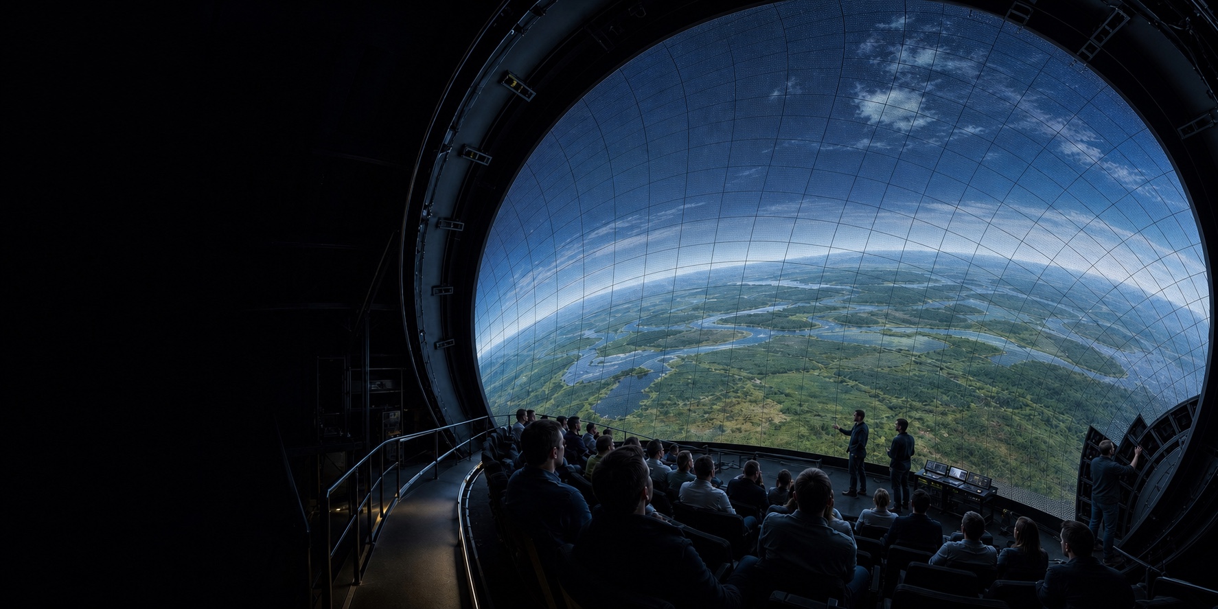
Audience eye points, field of view, nearest viewing distance, dome centre, tilt and crop define a buildable pixel surface.
Current development focus
NJ Endure applies compound-curvature geometry, supporting-structure and site-installation experience to inward-facing LED domes. Our present scope is feasibility, proof-of-concept work, carrier and interface engineering, and integration with qualified display partners.
Why the system boundary matters
Large LED domes add distributed heat, power, data, service access and substantial weight to a precision display surface. These disciplines must be resolved together before a pixel pitch or cabinet price becomes meaningful.
Audience eye points, field of view, nearest viewing distance, dome centre, tilt and crop define a buildable pixel surface.
A globally accurate sphere needs controlled cumulative error, adjustable interfaces and measured installation—not forced alignment on site.
Electrical zoning, airflow, controls and fault isolation are planned as part of the dome and building services.
Modules, power supplies and loudspeakers must remain reachable without compromising the image, sound field or fall protection.
Display-route decision
We assess both routes against the experience, building and operating model. LED is not an automatic upgrade, and projection is not a legacy default.
| Decision area | Perforated aluminium projection | Inward-facing LED |
|---|---|---|
| Best fit | Large areas, controlled light, established fulldome content and capital efficiency. | Premium contrast, multi-use venues, high brightness and reduced projector obstruction. |
| Facility impact | Relatively light screen; heat is concentrated around projection equipment. | Distributed power, heat, data and materially higher structural/service demands. |
| Audio | Mature perforated surface options for loudspeakers behind the image. | Requires an acoustically transparent module/cabinet architecture and installed-system testing. |
| Maintenance | Surface cleaning, local panel repair and projector maintenance. | Large populations of modules, power supplies and controls require access, spares and recalibration. |
| NJ scope | Established project-specific surface, structure, installation and acceptance package. | Feasibility, carrier/interface engineering, testing and partner-led integration. |
Large areas, controlled light, established fulldome content and capital efficiency.
Premium contrast, multi-use venues, high brightness and reduced projector obstruction.
Relatively light screen; heat is concentrated around projection equipment.
Distributed power, heat, data and materially higher structural/service demands.
Mature perforated surface options for loudspeakers behind the image.
Requires an acoustically transparent module/cabinet architecture and installed-system testing.
Surface cleaning, local panel repair and projector maintenance.
Large populations of modules, power supplies and controls require access, spares and recalibration.
Established project-specific surface, structure, installation and acceptance package.
Feasibility, carrier/interface engineering, testing and partner-led integration.
Engineering scope
Each workstream is version-controlled and assigned to NJ, the display partner, the AV team, the building engineer or the venue operator through a clear responsibility matrix.
Eye-point analysis, field of view, dome crop, target pitch, content resolution and minimum viewing distance.
Load paths, adjustable nodes, thermal movement, installation datums and survey/point-cloud acceptance.
Power modes, heat balance, airflow, zoning, grounding, protection, redundancy and monitoring.
Open area, insertion-loss data, loudspeaker distance and service access behind the image.
Front/rear service strategy, ladders or catwalks, fall protection, spare-part routes and digital asset numbering.
Pixel mapping, sync, colour/brightness calibration, burn-in, FAT/SAT and failure-recovery tests.
Stage-gated development
A project advances only when the geometry, partner architecture and measured prototype support the next commitment.
Compare LED and projection; define the display envelope, loads, utilities and budget corridor.
Freeze module, cabinet, control and IP responsibilities with a qualified display provider.
Build an equivalent-curvature section and measure geometry, heat, sound and maintainability.
Release coordinated structure, electrical, access, installation and acceptance documents.
Pre-assemble, burn in, install, survey, commission and hand over traceable records and spares.
Start a feasibility study
Early information can be incomplete. We identify assumptions explicitly and return a structured request for the missing decisions.
Begin with a technology-neutral feasibility study. We will define the geometry, interfaces, risks and partner inputs before a display architecture is locked.
Discuss an LED dome study →