Projection or LED for a Dome? A Systems-Level Decision Framework
The right dome display cannot be selected from contrast or pixel pitch alone. Projection and LED move cost and risk into different parts of the building, so the decision must be made at system level.
Editorial note. This analysis separates owner or procurement records, supplier statements and interpretation. Third-party projects are market evidence, not NJ Endure references.
“Projection or LED?” sounds like a display question. In a dome, it is a building, structure, acoustic, content and operating-model question.
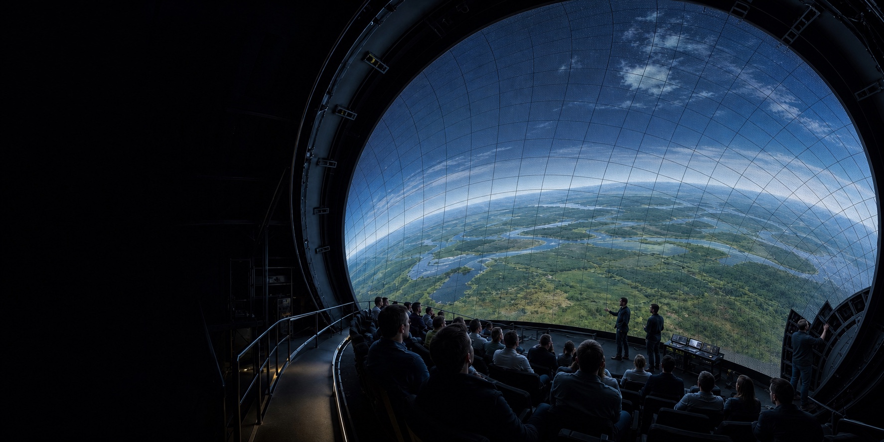
Direct-view LED can produce deep blacks and bright, high-contrast imagery without projection shadows. Projection can cover a very large area with a comparatively light, acoustically transparent surface and a mature fulldome ecosystem. Neither advantage settles the decision. Each route transfers complexity to a different part of the venue.
This framework is intended for concept and feasibility work. It is not a product ranking, and numerical values must come from shortlisted systems and the actual geometry.
Start with the experience, not the display
Before comparing technology, define a common performance brief:
- venue use: astronomy, giant-screen film, flying theatre, museum narrative, events or research;
- the complete audience eye-point cloud, including ride motion where applicable;
- dome diameter, tilt, opening, truncation and usable image area;
- minimum viewing distance and target angular resolution;
- content resolution, frame rate, dynamic range, 2D/3D and live-input needs;
- acceptable ambient light, emergency-light mode and cleaning-light mode;
- audio location, channel count and required acoustic transparency;
- building load, suspension or floor support, seismic and fire constraints;
- power, cooling, plant-room and maintenance capacity;
- opening date, planned closure windows and acceptable downtime;
- ten- or fifteen-year commercial use, attendance and content plan.
If vendors are comparing different image areas, brightness modes or audio layouts, their prices are not comparable.
The system-level comparison
| Decision area | Projected perforated aluminium | Direct-view LED dome | Evidence required before selection |
|---|---|---|---|
| Black level and contrast | Cross-reflection from one part of the dome can lift black level; projector and room-light control matter | Emissive pixels can produce stronger local black and contrast | Measured or simulated scene performance at agreed content levels—not headline contrast ratios |
| Brightness and uniformity | Depends on projector count, lenses, blending, surface gain and ageing | Depends on module output, calibration, viewing angle, thermal state and drive mode | Full-dome luminance and colour map at normal operating mode |
| Resolution | Determined by content, projector raster, overlap and angular pixel size | Determined by pixel pitch, module geometry and nearest viewer | Angular resolution from every priority eye point; visible-pixel and moiré review |
| Structure | Aluminium skin and frame are relatively light; projector positions need support and clear sightlines | Display, carrier, power/data and access can add substantial distributed mass | Load schedule, reaction forces, deflection and local-code calculations |
| Power and heat | Heat is concentrated mainly at projectors and equipment rooms | Heat is distributed behind a large display area; content level and brightness drive load | Normal and worst-case power, heat rejection and failure-mode analysis |
| Audio | Perforated surfaces have a mature behind-screen precedent but still introduce measurable loss | Requires acoustically transparent modules or an alternative speaker architecture | Installed insertion loss, frequency/phase response and speaker service plan |
| Maintenance | Surface cleaning/recoating; panel repair; projector consumables and alignment | Many modules, power supplies, receiving cards, cables and calibration states | Replacement path, spares policy, mean repair time and access simulation |
| Content | Established fulldome projection formats and workflows | Pixel map, HDR/brightness practice and display-specific mastering need validation | Test content through the complete playback pipeline |
| Obstruction and shadows | Projectors, ride vehicles or guests can cast shadows unless optically managed | No external projection rays across the audience volume | Combined eye-point, ride-envelope and optical model |
| Lifecycle change | Projectors can be replaced while retaining the surface or frame | Display generation, module matching and controller support are tightly coupled | Ten- or fifteen-year refresh scenario and contractual spares commitment |
The table exposes a recurring pattern: LED removes some optical risks but adds structural, thermal and electronic-service risks. Projection keeps the visible surface passive but requires careful light-path, reflectance and blend management.
Image performance: test the dome, not the brochure
Projection brightness is shaped by surface gain, incidence angle, projector overlap and inter-reflection. A high-reflectance coating can improve star brightness in one use case while worsening cross-bounce and black level in another. The International Planetarium Society configuration guide discusses why giant dome cinema and planetarium surfaces may use different reflectance ranges.
LED’s emissive black is a meaningful advantage, especially for dark scenes and venues with high contrast ambitions. But a dome also presents pixels at many angles. Module viewing angle, colour shift, scan architecture, calibration, low-grey performance and seam geometry need to be evaluated from multiple seats. A central demonstration position is insufficient.
For either route, request:
- luminance, colour and uniformity targets in the venue’s normal operating mode;
- test patterns and representative dark, bright and high-motion content;
- observation from the nearest, edge and moving eye points;
- performance after thermal stabilisation;
- acceptance thresholds and a repeatable measurement method.
Structure, weight and geometry
A projection dome is not weightless, but its image surface is passive. An LED dome adds modules, cabinets or carriers, power supplies, cabling and maintenance infrastructure across the display area.
Area grows with the square of radius. A complete hemisphere has area 2πr²: a 20 m-diameter hemisphere is about 628 m² before truncation or openings. Even modest kilograms or watts per square metre become building-scale quantities at that area.
The feasibility model must include:
- final cropped surface area, not nominal diameter alone;
- dead load by zone, live maintenance load and temporary installation load;
- seismic restraint and differential building movement;
- deflection and thermal movement limits driven by image quality, not only structural safety;
- adjustment range for accumulated radial and circumferential tolerance;
- delivery opening, lifting method and assembly sequence;
- paths for the largest replaceable module or panel.
For a flying theatre, the ride’s swept envelope and emergency recovery positions must share the same coordinate system. A “fit” at the home position is not a collision or visibility study.
Power, heat and mechanical systems
Projection typically concentrates electrical and cooling loads in projector or equipment locations. LED distributes power conversion and heat over the dome. The difference changes ducts, access, noise, fire detection and failure isolation.
A meaningful LED energy figure must state the tested brightness and image loading. “Average” power without a content assumption cannot size a venue. The calculation should cover:
- normal programme content and agreed luminance;
- a defined high-average-picture-level condition;
- maximum or commissioning mode;
- power-conversion, control and network losses;
- single-fan, blocked-filter and hot-day scenarios;
- heat entering the auditorium versus heat extracted behind the display;
- startup, emergency and selective shutdown logic.
The Prague Planetarium climate-control case study reports more than 70 kW of heat associated with its large LED dome and describes heat pumps, air handling, ground wells and extensive sensing. It is one project disclosure—not a coefficient for other domes—but it demonstrates why mechanical design belongs in the first feasibility gate.
Acoustics: “perforated” is not a result
Projected aluminium domes commonly place loudspeakers behind the screen. Open area reduces obstruction, but frequency response still depends on hole geometry, coating, incidence angle, speaker spacing, backing and cavity behaviour. Installed measurements and equalisation remain necessary.
LED presents a different challenge. If the display product is acoustically open, the team needs third-party or witnessed measurements over the relevant frequency range and at relevant angles. If speakers are not behind the display, the design must demonstrate that apparent sound location still follows the image throughout the audience or ride motion.
For both routes, the acceptance plan should include:
- insertion loss and frequency response before and after the image surface;
- time and phase behaviour where spatial audio depends on it;
- structure-borne noise and rattles;
- HVAC noise at normal and high load;
- access to drivers without dismantling an impractical area of screen.
Operations, spares and technology refresh
A passive aluminium surface has a long mechanical life, but its coating accumulates dust and may eventually require cleaning, recoating or repanelling. Projectors have their own optical-engine, light-source, filter and alignment cycles.
An LED dome replaces those projection assets with a large electronic estate. A maintainable design needs:
- module, receiving-card and power-supply addressing tied to an as-built model;
- safe front, rear or hybrid access;
- spares from matched production batches;
- a plan for calibration after replacement;
- accepted definitions for dead pixels, dark lines, colour difference and downtime;
- long-term controller, firmware and component support;
- a route to replace technology without discarding avoidable structure.
Neither route is maintenance-free. The useful comparison is labour, closure time, parts risk and performance recovery over the planned operating period.
Content and commercial use
Technology value depends on what the venue can programme. Projection benefits from a mature fulldome content and distribution ecosystem. LED can enable high contrast, live events and content that would be compromised by shadows, but existing fulldome material still needs to be tested for pixel mapping, brightness, grading and playback.
An LED investment may make sense for a flagship venue that can use the dome throughout the day for education, premium cinema, concerts, corporate hire and live visualisation. It is harder to justify if the content calendar is sparse or the building cannot support the operating cost.
Conversely, retaining projection is not automatically conservative. A new laser system, measured surface intervention and modern audio may produce a compelling upgrade while preserving building structure and content workflow.
Reading early LED outcomes carefully
The Fort Worth Museum of Science and History project page describes a 23 m, 8K-plus LED dome and reports increased school visitation and near-capacity weekends after its 2024 opening. Those are relevant signals, but they are published by the technology supplier. They do not isolate the dome from reopening effects, programming, marketing or broader museum changes, and they should not be treated as a guaranteed revenue uplift for another venue.
A proper business case needs venue-specific attendance scenarios, ticket yield, programming cost, utilisation, sponsorship, operating expense and downside sensitivity.
A four-gate feasibility process
Gate 1 — Common geometry and experience brief
Freeze the audience and ride eye points, surface, content uses, audio intent and acceptance priorities. Reject comparisons based on inconsistent coverage.
Gate 2 — Two concept designs
Develop projection and LED concepts far enough to expose structure, optical or pixel performance, audio, HVAC, power, access and construction sequence. Vendor budget quotes without these interfaces are only placeholders.
Gate 3 — Lifecycle and commercial model
Compare capital cost, enabling building work, energy, planned maintenance, spares, closure, content conversion and at least one technology refresh. Test optimistic, base and downside attendance cases.
Gate 4 — Demonstration and risk retirement
Use representative geometry or viewing angles, not only a flat showroom wall. Witness low-grey, motion, thermal and acoustic performance; agree acceptance metrics; and resolve local engineering responsibility before award.
The conclusion may still be LED, projection or a phased route. The value of the process is that the choice follows the venue’s evidence instead of the current technology narrative.